Good Vibrations – Shock- and vibration resistance of sensors

Sensors in industrial environments are usually exposed to shock and vibration loads. To ensure that the sensors can withstand such loads without damage, shock and vibration tests are carried out and values such as 150 g/11 ms and 30 g/10...2000 Hz are specified in the technical data. To explain these values, we will first clarify the following question:
What is a shock?
A shock is a single short-time high impact load. Such a load occurs, for example, when an object falling from a table hits the floor. The more rigid the object and the floor are, the higher the shock applied to the object. If an object falls from a height of 75 cm onto a carpeted floor and is decelerated within 5 mm due to the carpet, the load on the object is 150 g. The load of a shock is given as a multiple of the acceleration due to gravity g (g = 9.81 m/s²). A car crashing at 137 km/h against a rigid wall and whose crumple zone is compressed by 50 cm will also get a load of 150 g. A human being cannot survive a load of 150 g unharmed. For the human organism, loads of 15...20 g seem possible without danger (This applies when the acceleration acts perpendicular to the body axis).
What is a shock test?
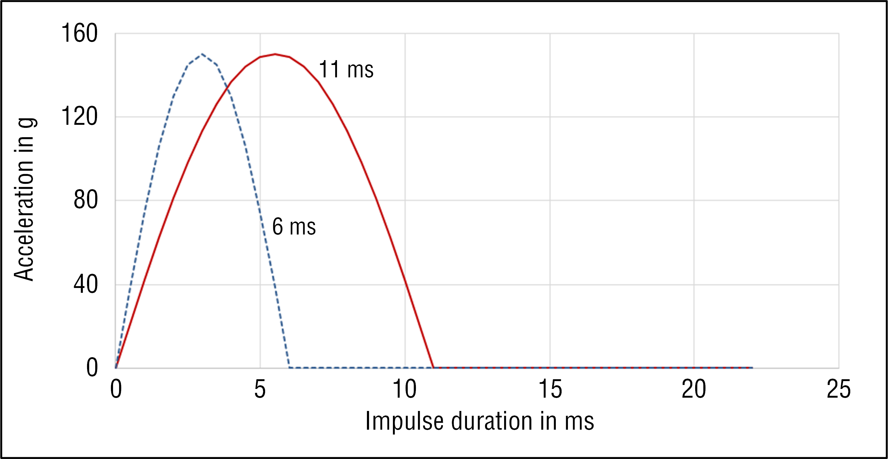
In shock tests, a test specimen is subjected to a certain shock and it is checked whether the test specimen survives this shock without damage. In such a test, there are different types of shocks, which differ in terms of their shape, such as half-sine, saw tooth and trapezoidal. The most commonly used shock type is the half-sine shock. This type of shock simulates an impact that occurs during the acceleration and deceleration of vibrating parts. In addition to the acceleration, a shock test also specifies the impulse duration of the shock. Fig. 1 shows two half-sinusoidal shocks with the same acceleration and different impulse durations.

Fig. 1: Curve of a half-sine shock with 150 g/6 ms and 150 g/11 ms
A sensor such as the R-Series V can withstand a shock load with an acceleration of 150 g at an impulse duration of 11 ms (red continuous curve in Fig. 1) without damage. Sensors are also frequently tested with a shock of 150 g/6 ms (blue dashed curve in Fig. 1). The difference between these two half-sine shocks becomes clear when looking at the area below the curves. This area represents the velocity at the end of the acceleration pulse (integration of an acceleration gives the velocity). The area below the red curve is larger by a factor 11 ms /6ms = 1.83 compared to the area below the blue curve. If comparing the two half-sine shocks with respect to the kinetic energy, the energy of the red curve is higher than that of the blue curve by a factor of (11 ms/6ms)2 = 1,832 = 3.36, because the velocity enters quadratically in the energetic consideration (Energy E = 0,5m*v2 with mass m and velocity v).
What is vibration?
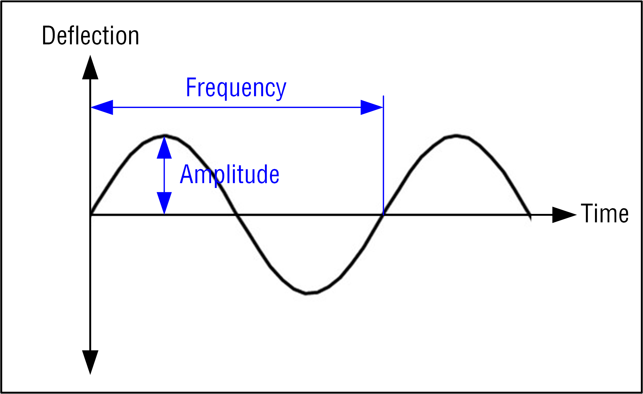
A vibration, such as shaking a tree to harvest fruit, is an oscillation. As shown in Fig. 2, an oscillation is described by its amplitude as well as its frequency. In the industrial environment, vibrations occur, for example, on machines with rotating elements or on conveyor belts. These vibrations are transmitted to components mounted to the machine. In a vibration, the amplitude of the load is specified as acceleration and the acceleration is specified as a multiple of the acceleration due to gravi ty g, as in the case of shock.

Fig. 2: Oscillation with amplitude and frequency
What is a vibration test?
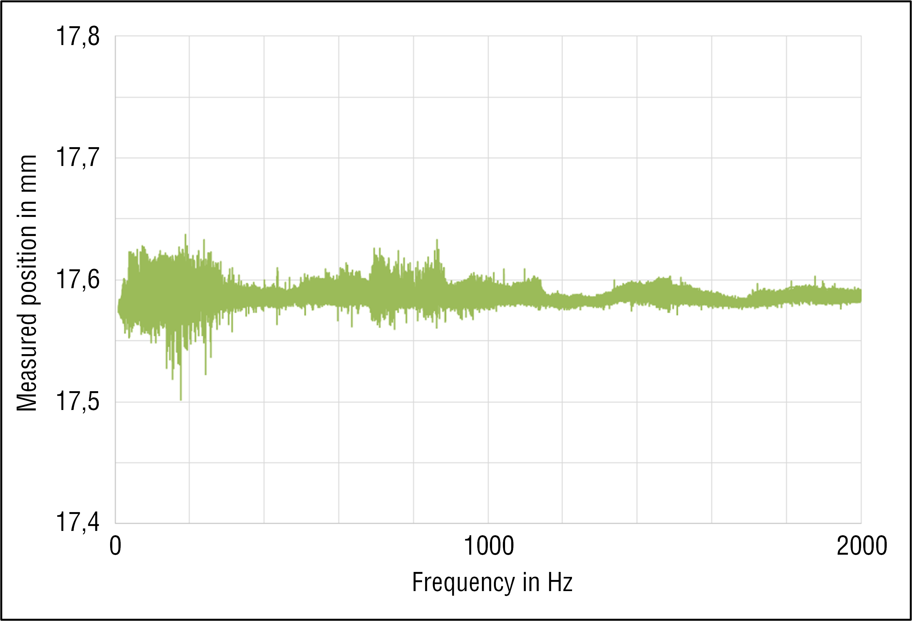
In vibration testing, a specified acceleration is applied to a test specimen over a frequency band. The acceleration is lower than in the shock test and is, for example, 30 g. For a load of 30 g, the object falls from a height of 15 cm onto the carpet, which yields 5 mm. Or the car hits against a rigid wall with 62 km/h, whereby the crumple zone is compressed by 50 cm. This acceleration is applied to the test specimen in frequencies of, for example, 10...2000 Hz. This frequency range is roughly comparable to the range of a piano from the lowest note to the highest note (The frequency range of a piano with 88 keys is approximately 27…4000 Hz).

Fig. 3: Position measured by a magnetostrictive sensor at a vibration of 30 g over a frequency of 10…2000 Hz
Why are such tests performed?
Shocks and vibrations occur in industrial environments, whether during transport or when used in a machine. However, these loads should not damage the sensors – just as when a tree is shaken, hopefully only the fruit falls and no branches. Shock and vibration tests simulate these loads in an industrial environment so that weak points can be identified and remedied in advance. Sensors such as the R-Series V are tested for shock and vibration as part of the development process to ensure that the sensors will function properly when used in such conditions.
If shock and vibration are known at the point of use, sensors can be selected to meet these requirements. If sensors are used that have high shock and vibration resistance, measures for damping can be minimized or eliminated completely. Even in the event of unexpected shock and vibration loads, a sensor such as the R-Series V provides certainty, since the sensor can withstand the loads even in such cases due to its shock and vibration resistance.
GET IN TOUCH WITH US
You have a question about one of our products or would like more details on a possible application?
Click here to fill in our request form
Don't want to miss out on the latest blog updates and other news?
Click here to subscribe to our newsletter
Total customer satisfaction
We live by the promise of unparalleled service that
enables us to take all available means to exceed your expectations.
Click here to find out how we support our customers

