Analog signal transmisson: Outdated or contemporary?
Current or voltage?
With an analog output, the user can usually choose between current or voltage output. Depending on the choice, the measured variable, such as position, is transmitted to the controller as a continuously running current or voltage signal. In case of a magnetostrictive sensor with analog output such as the R-Series V Analog, the stroke length is mapped to a range of e.g. 0…20 mA or 4…20 mA or 0…10 V or –10…+10 V. The main characteristics of current and voltage signal are:
- Voltage signals can be measured easily
- When measuring a current signal the circuit must be opened
- Voltage signals are attenuated over longer distances due to the wire resistance
- Current signals do not generally become weaker over long distances
- Current signals are insensitive to electromagnetic interference
- With current signal of 4…20 mA, a defective wire leads to current flow of 0 mA, so cable faults can be quickly detected
Analog or digital?
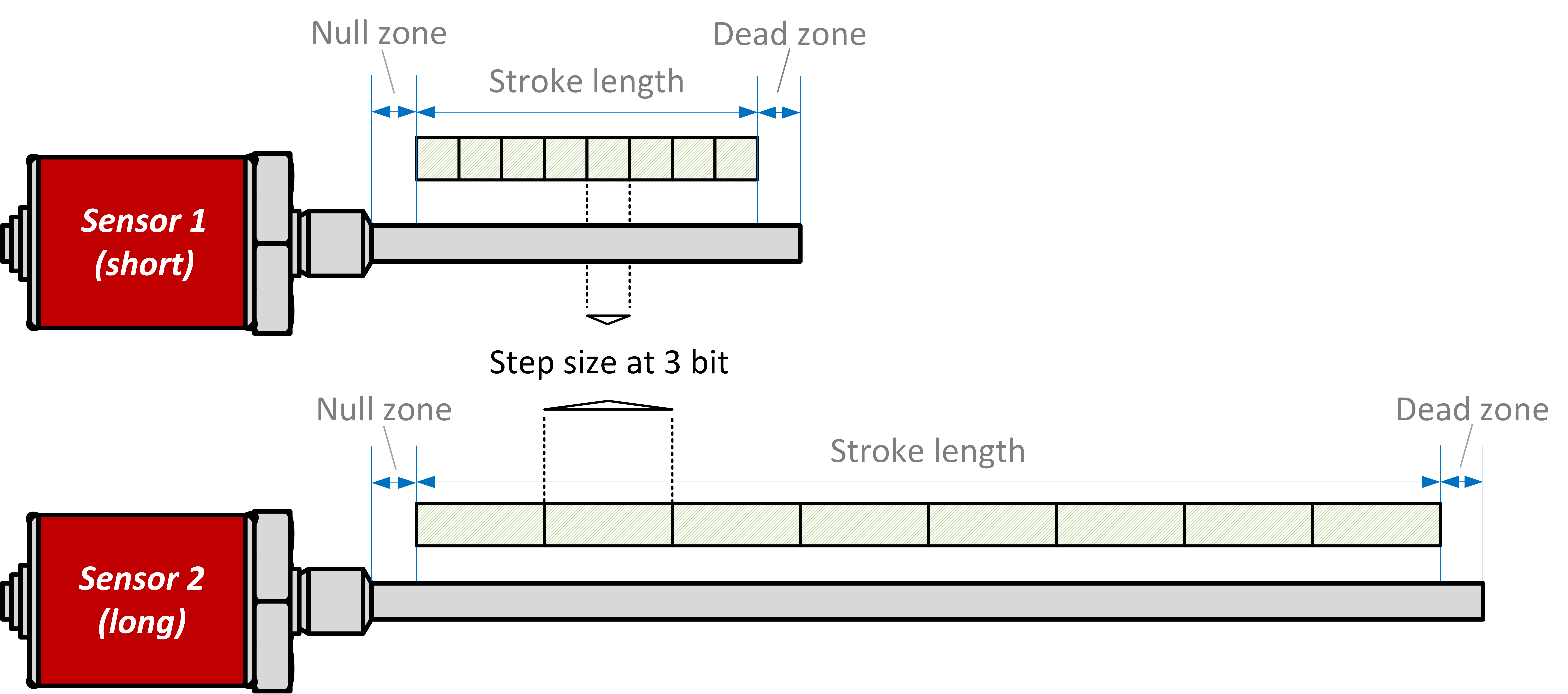
For a sensor like the R-Series V Analog, a resolution of 16 bit is specified in the technical data. Why is a digital value for the resolution specified for an analog output? With the R-Series V Analog, the measured value is available as the result of the position determination within the sensor in digital form with a resolution of 0.1 µm. This digital value is converted into a voltage or current signal for the analog output using a digital to analog converter (DAC). The DAC used in the R-Series V Analog has a resolution of 16 bit. This means that the converter can map 216 = 65,535 different gradations, meaning the stroke length of the sensor is divided into 65,535 equal steps. This is shown schematically in Fig. 1 for two sensors with different stroke lengths. In this example, the stroke length of the two sensors is mapped with a resolution of 3 bit = 23 = 8 steps.

Fig. 1: Dependence of the step size on the stroke length at a resolution of 3 bit
Table 1 lists the step size as a function of the meauserement length for a 16 bit D/A converter (the measurement length is distributed evenly over the available 65,535 steps):
| Stroke length | Step size |
|---|---|
| 25 mm | 0.4 µm |
| 65.5 mm | 1 µm |
| 2,000 mm | 31 µm |
| 7,620 mm | 116 µm |
Table 1: Step size as a function of the measuring length for a 16 bit D/A converter
The step size therefore increases with increasing stroke length. Conversely, this means that the smaller the stroke length, the smaller the step size. And the smaller the step size, the more finer position changes are registered.
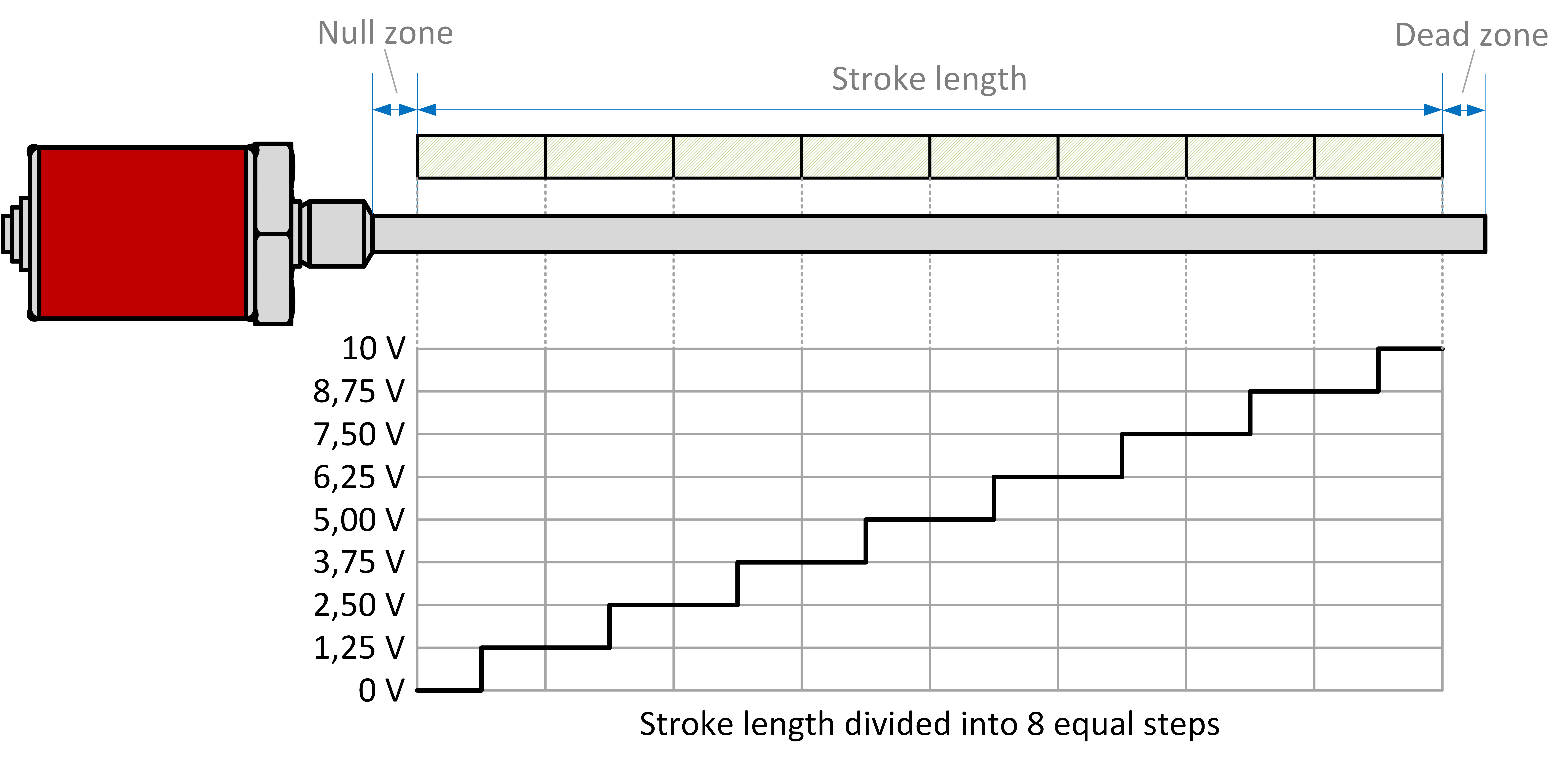
An analog signal is generated from the evenly distributed steps. This is shown in Fig. 2 for a voltage signal of 0…10 V at a resolution of 3 bit. In this example, each step causes a voltage change of 1.25 V. For the R-Series V Analog with 16 bit resolution, one step at a voltage signal of 0…10 V causes a voltage change of (10 V / 65,536 steps) = 150 µV. This applies in the same way to the current output. For example, with the current output of 4…20 mA, the available 16 mA are distributed over the 65,535 steps. Thus, one step provides a current change of (16 mA / 65,535 steps) = 244 nA. This means that the measuring instrument or controller must have a resolution in the range of nA or μV regardless of the stroke length of the sensor to register the measured position changes.

Fig. 2: Conversion into an analog signal using the example of a voltage signal of 0...10 V
Speed or velocity?
With the R-Series V Analog, as with the R-Series 2004 Analog, in addition to position the speed or velocity at which the position magnet moves can be reported via an additional channel. The user can choose between speed and velocity. Speed means that an absolute value is reported for how fast the position magnet is moved, regardless of the measurement direction. With velocity, the analog value is also used to report in which direction the position magnet is moved, i.e. whether it is moving forwards or reverse.
Analog or Industrial Ethernet?
As already mentioned, the analog output can be described as a traditional signal type because this type of signal transmission has been used in industrial environments for a very long time. In addition to the analog output, Industrial Ethernet interfaces such as EtherCAT®, EtherNet/IP™, POWERLINK or PROFINET have also become established. The table 2 compares the essential differences between analog signal transmission and Industrial Ethernet interfaces.
Based on Table 2, it is clear that Industrial Ethernet interfaces can do more than an analog output (transmission of several pieces of information simultaneously, bidirectional communication between sensor and controller e.g. for parameter adjustment, synchronous measurement for motion control applications, support of different topologies for flexible setup). This makes these interfaces much more complex than analog signal transmission, which also affects installation and inspection.
| Feature | Analog signal transmission | Industrial-Ethernet-interface |
|---|---|---|
| Possibility to inspect the transmitted signal | Connection to multimeter | Connection to control |
| Supported topology | Star | Line, tree, star, ring |
| Cabeling | 1 cable per sensor | 3 cables per sensor: 2 × data line + 1 × power supply |
| Cable length | > 100 m possible | Maximum 100 m without additional devices |
| Transmitted information | Only 1 function, e.g. position | Various functions, e.g. positon, velocity and status information, simultaneously |
| Communication direction | Unidirectional: only from sensor to control | Bidirectional: from sensor to control and from control to sensor |
| Minimum resolution | Depending on stroke length | Independent from stroke length |
| Synchronization for data acquisition | Not possible | possible |
Table 2: Comparison of essential features of analog signal transmission and Industrial Ethernet interfaces
There are many applications where analog signal transmission is very well suited and can bring its advantages over Industrial Ethernet interfaces, such as ship locks: Lock systems for self-proppeld barges are usually larger than 100 m, which is why analog signal transmission is often used here. In addition, an accuracy in the millimeter range is sufficient, e.g., when moving lock gates, so that the advantage can be taken of being able to easily check the transmitted signal on site with a multimeter.
Outdated or contemporary?
The question of the suitable transmission type depends on the application and the operational environment. Both analog signal transmission and Industrial Ethernet interfaces (as well as data transmission via SSI) have proven and established themselves in the industrial environment. In advance, the user must clarify which transmission type is suitable for his application so that he can make the appropriate choice for his application.
Author: Olaf Kissing, Product Manager Industrial Sensors
GET IN TOUCH WITH US
You have a question about one of our products or would like more details on a possible application?
Click here to fill in our request form
Don't want to miss out on the latest blog updates and other news?
Click here to subscribe to our newsletter
Total customer satisfaction
We live by the promise of unparalleled service that
enables us to take all available means to exceed your expectations.
Click here to find out how we support our customers

