A
- Absolute position
-
The sensor’s output indicates the position relatively to an absolute (fixed) reference point. Immediately after power is applied, there is no need to “rehome” the sensor as you would with one that provides an incremental position output.
- Alarm
-
The alarm bit is set by the sensor if the sensor detects more magnets (extra magnet) or less magnets (magnet status error) than configured.
- Ambient condition
-
Environmental conditions, under which transducers must commonly operate, which have been established as follows: a) temperature: 25 °C (± 10 K) b) relative humidity: < 90 % Tolerance closer than shown are frequently specified for transducer calibration and test environments.
- Analog output
-
For a sensor with analog output, the measured value is output as an analog voltage signal or current signal.
- Asynchronous mode
-
Asynchronous data communication occurs when data is sent from one device with its own clock to another device with a separate clock. When a Temposonics® position sensor is used in the asynchronous mode, the sensor takes measurements at its fastest internal interrogation rate (length dependent) and provides the information upon request.
C
- CAM
-
Cam position of a CAM channel in a cam gear. Each CAM position can be configured separately. With R-Series V POWERLINK, for each position magnet there is one CAM channel. Each CAM channel supports up to four CAM positions.
- CIP Sync™
-
Synchronization services in CIP (Common Industrial Protcol) provide the increased control coordination to achieve real-time synchronization between distributed devices and systems. CIP Sync™ is compliant with IEEE-1588™ standard and allows synchronization accuracy between two devices of fewer than 100 nanoseconds.
- Closed Error Signal Utility
-
At very high shock or vibration events, the magnet may no longer be detected properly. For these error events the Closed Error Signal Utility will produce an output signal waveform that corresponds to a value of just over the 100 % full stroke position. Contact Applications Engineering for more information.
- Controlled Node (CN)
-
All devices in the network, except the Managing Node, are Controlled Nodes (CN). The Controlled Nodes may send their data only after being requested by the Managing Node. The R-Series V POWERLINK can only be used as a Controlled Node. (→ Managing Node)
D
- Differential measurement
-
For differential measurement, the distance between the two position magnets is output as a value.
- Distributed Clock
-
EtherCAT® uses a logical network of Distributed Clocks (DC) to synchronize the time on all local bus devices on the network. The EtherCAT® master usually selects the first Distributed Clock capable slave device as a Reference Clock, and then maintains a precise mapping of frame delays for all other slave devices in order to adjust their time to match the system time. (→ Free Run, → Synchronous to SyncManager Event)
- DLR
-
The Device Level Ring (DLR) protocol provides a means for detecting, managing and recovering from faults in a ring-based network.
- Drift
-
Drift is the change in the output signal or output value under enviromental impact e.g. time or temperature. See also warm-up and temperature coefficient.
E
- EDS
-
The properties and functions of an EtherNet/IP™ device are described in an EDS file (Electronic Data Sheet). The XML-based EDS file contains all relevant data that are important for the implementation of the device in the controller as well as for data exchange during operation. The EDS file of the R-Series V EtherNet/IP™ is available on the homepage www.temposonics.com.
- Encoder Profile
-
The encoder profile corresponds to the specification of the encoder profile V4.2 (PNO no. 3.162). With this profile, the position and the velocity of one magnet can be measured and transferred simultaneously. (→ Linear Profile).
- ESI
-
The properties and functions of an EtherCAT® device are described in an ESI file (EtherCAT® Slave Information). The XML-based ESI file contains all relevant data that are important for the implementation of the device in the controller as well as for data exchange during operation. The ESI file of the R-Series V EtherCAT® is available on the homepage www.temposonics.com.
- EtherCAT
-
EtherCAT® (Ethernet for Control Automation Technology) is an Industrial Ethernet interface and is managed by the EtherCAT® Technology Group (ETG). The R-Series V EtherCAT® and its corresponding ESI fi le are certitifi ed by the ETG.
- EtherNet/IP™
-
EtherNet/IP™ (Ethernet Industrial Protocol) is an Industrial Ethernet interface and is managed by the Open DeviceNet Vendor Association (ODVA). The R-Series V EtherNet/IP™ and its corresponding EDS file are certitified by the ODVA.
- External Interrogation
-
For a sensor that is configured for external interrogation, a signal is required from the controller or interface module to initiate every measurement cycle.
- Extrapolation
-
The native measurement cycle time of a sensor increases with the stroke length. With extrapolation, the sensor is able to report data faster than the native cycle time, independent of the stroke length of the sensor. Without extrapolation, if data is requested faster than the native cycle time, the last measured value is repeated.
F
- FIR Filter
-
The FIR filter (Finite Impulse Response) is used to smooth the measured position value before output. To determine the output value, only input values corresponding to the window (filter window size) are used for filter calculation. The output value is calculated from these input values in the form of a moving average value. (→ IIR Filter)
- Free Run
-
The sensor operates autonomously based on its own cycle and is not synchronized with the EtherCAT® cycle.
(→ Distributed Clock, → Synchronous to SyncManager Event) - Full Scale (F.S.)
-
See “Range”
G
- Gradient
-
The gradient is the inverse of the rate at which a strain pulse propagates through the magnetostrictive waveguide, (velocity of propagation ≈ 2780 m/s). The gradient values will vary slightly from sensor to sensor. The actual measured gradient values for some sensors are indicated on the label attached to the sensor.
- GSDML
-
The properties and functions of a PROFINET IO field device are described in a GSDML file (General Station Description). The XMLbased GSDML file contains all relevant data that are important for the implementation of the device in the controller as well as for data exchange during operation. The GSDML file of the R-Series V PROFINET is available on the homepage www.temposonics.com.
H
- Hysteresis
-
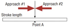
The difference in indicated position for the same point along a stroke length when reached from opposing directions. Note: The hysteresis specification for Temposonics® position sensors is minimal and can be ignored, in most applications.
I
- I/O Mapping
-
I/O mapping is used to configure the cyclical data that is transferred between sensor and controller. The assignment of the inputs (IN) and outputs (OUT) is done from the perspective of the controller. Cyclical data from the sensor to the controller are, for example, the position and the velocity.
- IIR Filter
-
The IIR filter (Infinite Impulse Response) is used to smooth the measured position value before output. To determine the output value, the input values corresponding to the filter grade (filter window size) are used for the filter calculation. The previous values are also taken into account when calculating the output value. (→ FIR Filter)
- Internal Interrogation
-
For a sensor that is configured for internal interrogation, no signal is needed from the controller as the sensor itself initiates the next measurement cycle upon the completion of the current cycle.
- Internal Linearization
-
The internal linearization offers an improved linearity for an overall higher accuracy of the position measurement. The internal linearization is set for the sensor during production.
- IRT
-
With PROFINET IRT (Isochronous Real Time) a clock-synchronous data transmission takes place. The application, the data transmission as well as the device cycle are synchronous. IRT enables a clock-synchronous data exchange with a minimum cycle time of 250 μs in the network. The R-Series V PROFINET supports PROFINET RT and IRT. (→ RT)
L
- Linear Profile
-
The linear profile was developed by Temposonics and is tailored to the characteristics of magnetostrictive position sensors. With this profile, the positions and velocities of up to 30 magnets can be reported and transferred simultaneously. (→ Encoder Profile)
- Load impedance
-
The impedance presented to the output terminals of a transducer by the associated external circuitry.
M
- Managing Node (MN)
-
The Managing Node (MN), usually an industrial PC or a PLC, controls the communication in the network as master and sets the clock for the synchronization of all devices. In a network there is only one Managing Node. All other devices of the POWERLINK network are Controlled Nodes. (→ Controlled Node)
- Max. speed or velocity value
-
For speed or velocity, the output value generated is scaled based on the maximum speed or velocity value indicated in the order code.
- Measuring Direction
-
When moving the position magnet, the position and velocity values increase in the measuring direction.
• Forward: Values increasing from sensor electronics housing to rod end/profile end
• Reverse: Values increasing from rod end/profile end to sensor electronics housing - Multi-position measurement
-
Multiple magnets located at several positions along the stroke can be used to measure multiple positions simultaneously. Temposonics® R-Series V products can measure 20 positions on a single sensor.
N
- Node ID
-
The addressing of the devices in a POWERLINK network is done via the node ID. Each node ID only exists once in a network. It can have a value between 1 and 240 (while 240 is reserved for the Managing Node). Meaning that a POWERLINK network can comprise up to 240 devices. With the R-Series V POWERLINK, the node ID (delivered with node ID 1) can be set via the TempoLink® smart assistant, for example.
- Non-contact
-
Temposonics® position sensors utilize a non-contact sensing technology that results in longer-lasting sensors with greater reliability and no mechanical wear.
- Non-linearity
-
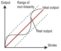
The degree that the indicated position of the magnet at points along the stroke length of the sensor varies from the actual physical position. In magnetostrictive sensors, this variability is caused by minute differences in the propagation rate of the return signals through the waveguide medium. Non-linearity is expressed in absolute error or as a percentage of the active stroke length.
O
- Offset
-
A value which will be added or deducted to the actual position value. This leads to a shift of the measurement range start. (→ Preset)
- Outputs
-
- Digitally-derived analog output:
A digital position count of 16 bits is converted to an analog signal (voltage or current) via a digital/analog converter.
- Digital output: PROFINET, EtherCAT®, EtherNet/IP ™, POWERLINK, SSI, CANopen, IO-Link, CANbus, Start/Stop, Profibus
An internal counter is used to precisely measure the time interval between the launching of an interrogation pulse and the receipt of a return signal. The time interval, detected in counts, is then supplied to the customer’s interface via the chosen format or protocol above.
- Over range output mode
-
When enabled this mode allows the position output values to continue to increase or decrease when the magnet travels beyond the active stroke range.
P
- Parity
-
The parity bit is a check bit that is added to a bit string to detect transmission errors. There are even parity and odd parity. With even parity, the parity bit is set so that the total number of 1-bits in the bit string including the parity bit is even. In case of odd parity, the total number of 1-bits in the bit sequence including the parity bit is odd. Even parity is implemented in the R-Series V SSI.
- PLC
-
A PLC (Programmable Logic Controller) is a device for controlling or regulating machines and systems.
- POWERLINK
-
POWERLINK is an Industrial Ethernet interface and is managed by the Ethernet POWERLINK Standardization Group (EPSG). The R-Series V POWERLINK and its corresponding XDD file are certitified by the EPSG.
- Preset
-
With the preset, a value is entered for the current position which is to be output at this position in the future. The difference between the entered value and the currently measured position is calculated as an offset. (→ Offset)
- PROFINET
-
PROFINET (Process Field Network) is an Industrial Ethernet interface and is managed by the PROFIBUS Nutzerorganiation e.V. (PNO). The R-Series V PROFINET and its corresponding GSDML file are certitified by the PNO.
- Pulse width modulation (PWM)
-
With pulse width modulation, the position of the magnet is determined »X« times according to the number of circulations after the start of the measurement. The number of circulations »X« is specified in the order code of the sensor. The measurement is stopped after these »X« position determinations have been completed. The time between the start and end of the measurement is measured in the controller. Since the controller knows the number of circulations »X«, it calculates the magnets position on the sensor rod/sensor profile from the number of circulations »X« and the measured time. This procedure increases the resolution of the measurement and extends the duration of a measurement.
R
- Range
-
The measurands, over which a sensor is intended to measure, specified by their upper and lower limits.
- Repeatability
-
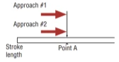
The deviation in indicated position when a point along a stroke length is approached repeatedly from the same direction. For an example, see the illustration below.
If you leave point “A” and then return to it from the same direction as before, the change in indicated position between the two readings is described by the repeatability specification. For magnetostrictive sensors, repeatability is usually equal to resolution.
- Resolution
-
The term resolution describes the smallest incremental change in position along the stroke length that can be detected and indicated in an output. For digital systems resolution is a discrete value corresponding to one binary bit out of the total number of bits used in the output.
- Resolution and data length depending on stroke length
-
The stroke length of the sensor influences the choice of resolution and data length. The resolution (step size) and data length (number of steps) must be selected so that the stroke length is covered. For example, with a data width of 24 bit and a resolution of 0.5 µm for an RH5 sensor the maximum stroke length of 7620 mm can be represented. You can adjust the resolution and the data length of the R-Series V SSI via the TempoLink® and TempoGate® smart assistants.
- RO
-
RO (Read Only) means that the value of the variable can only be read but is not modifiable.
- RT
-
With PROFINET RT (Real Time) the data exchange is without clock synchronization. In this case, the application, the data transmission and the field devices operate according to their own processing cycle. The R-Series V PROFINET supports PROFINET RT and IRT. (→ IRT)
- RW
-
RW (Read/Write) means that the value of the variable can be read and written. The value of the variable is modifiable.
S
- Speed
-
The output value for speed indicates how fast the position magnet is being moved, independent of the measuring direction. (→ Velocity)
- Start/Stop
-
With the Start/Stop interface, the sensor receives a start pulse from the controller and sends back a stop pulse at the end of the measurement. The time between the start and stop pulse is proportional to the position of the magnet on the sensor rod/sensor profile. As the time measurement takes place in the controller, the time resolution of the controller unit determines the position resolution.
- Synchronous mode
-
In synchronous mode the measurement and output of the sensor is matched to the data request cycle of the controller. The synchronous mode minimizes the time delay between measurement and output. The synchronous mode is required for sophisticated motion control applications. (→ Asynchronous mode)
• Synchronous mode 1 Using synchronous mode 1, the sensor determines the controller’s loop timing and when data is being requested. The sensor then determines when to start the next measurement cycle so that it will complete just in time to deliver the freshest data possible.
• Synchronous mode 2 If new position data is required faster than the sensor’s measurement cycle time, synchronous mode 2 provides extrapolated data values, calculated on the fly. A measurement value will be calculated and output to the controller whenever the sensor has not yet completed the next measurement cycle.
• Synchronous mode 3 Synchronous mode 3 provides an extrapolation to the high speed update feature of synchronous mode 2. For this mode all measurements values which are output are calculated to fully compensate for the inherent lag time due to the sensor’s measurement cycle. (→ Extrapolation) - Synchronous Serial Interface
-
SSI (Synchronous Serial Interface) is a digital interface where the data is transferred serially. The interface of R-Series V SSI corresponds to SSI industry standard for absolute encoders. Its displacement value is encoded in a 24/25/26 bit binary or gray format and transmitted as a differential signal in SSI standard (RS-485/RS-422).
- Synchronous to SyncManager Event
-
Besides the “Free Run” mode and the “Distributed Clock” DC mode, the sensor can be operated in the mode “Synchronous to SyncManager (SM) Event”. The SM event is triggered by the SyncManager when a passing frame is processed. (→ Distributed Clock, → Free Run)
T
- Temperature Coefficient (TC)
-
Temperature Coefficient (TC) is expressed as ppm/°C (ppm = parts per million).
TC is the degree to which the indicated position is affected by ambient temperature changes.
Example (Sensor with analog output): Output: 0 to 10 VDC / Stroke length: 200 mm / Temperature change: 5 °C / TC= 25 ppm/°C If the indicated output at 200 mm is 10 VDC, the potential change in indicated output per degree in Celsius. Temperature change is 1.25 mV or 0.025 mm for a 5 °C rise.
Temperature in the sensor electronics housing
The temperature in the sensor electronics housing is measured in °C. With this option, the transmitted data word has a length of 32 bits, with the highest 8 bits representing the temperature value, followed by 24 bits for the position value. The temperature value is coded in the same format as the position value.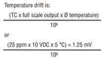
- Temperature in the Sensor Electronics Housing
-
The temperature in the sensor electronics housing is measured in °C. With this option, the transmitted data word is 32 bits long, with the highest 8 bits representing the temperature value, followed by 24 bits for the position value. The temperature value is encoded in the same format as the position value.
- TwinCAT
-
TwinCAT (The Windows Control and Automation Technology) is an automation solution from Beckhoff Automation GmbH & Co. KG for operating an EtherCAT® network.
V
- Velocity
-
The output value for velocity indicates how fast the position magnet is being moved, and in which direction. (→ Speed)
- Vendor ID
-
A unique identification number (ID) assigned to each piece of computer hardware.
W
- Warm-up period
-
The time required for the output to stabilize following power-up of the sensor.
This error is characterized by a parallel position of the entire calibration curve. - WO
-
WO (Write Only) means that the value can only be written.
X
- XDD file
-
The properties and functions of a POWERLINK device are described in a XDD file (XML Device Description). The XML-based XDD file contains all relevant data that are important for the implementation of the device in the controller as well as for data exchange during operation. The XDD file of the R-Series V POWERLINK is available on the homepage www.temposonics.com.